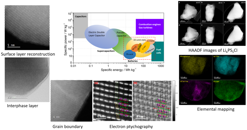
The world's energy-storage strategies are currently shaped by battery technologies in terms of the advantages in both specific energy (energy density) and specific power (power density). Figure 1 shows a Ragone plot of various kinds of electrochemical energy storage devices in comparison with combustion engines and gas turbines. Batteries of different configurations show high potential to replace traditional combustion engines and lower the consumption of fossil fuels. Indeed, Li-ion batteries have been widely used in electric vehicles. Advancing the performance of batteries relies on the development of new materials.
In general, batteries contain four main components, namely the cathode, anode, electrolyte and separator. To further advance the battery performance, we need to understand the properties of these materials and then further develop them. Electron microscopy and spectroscopy provide unique local structure and elemental information of the materials from the nanoscale to beyond the sub-angstrom scale. This information can help us to understand the change in the phase, strain, chemical bonding, element distribution and electronic structure of materials during electrochemical reactions.

Figure 1
We are interested in the characterization of materials and interfaces in various kinds of battery configurations, such as Li-ion batteries, all-solid-state batteries, Li-sulphur batteries, Li-metal batteries and multivalent batteries. We are participating in two Faraday Institution projects, namely SOLBAT and CATMAT. In SOLBAT, we are studying solid electrolytes, electrolyte/electrolyte interface and Li-metal anodes. In CATMAT, we are particularly interested in the study of Li-rich layered metal oxides and disordered rocksalt metal oxides.
Battery materials are very beam sensitive. To minimize the beam damage, we have developed a low-dose and low-atomic-number imaging technique called electron ptychography. Battery materials are also air sensitive. We use a variety of TEM holders to handle these specimens, including an air-free transfer TEM holder and a Cryo TEM holder (Figure 2).

Figure 2